
Making the I2C work with the new HAL library on ARM Cortex Mx (STM32Fxx) Processor
 |
| Added 1.5K pull-up resistors (R3, R4) on the I2C line (SCLK, SDA) |
I had an important breakthrough today with my code, so I decided I might as well document it. Unfortunately, the post will skew very far from the normal writings I do here. If, however, you are interested in embedded coding, there might be something for you.
Just keep calm and keep reading.
But before I go any further on writing about how made finally made the I2C to respond the way I liked, I have to talk about something that's bothering me since this morning.
My Hair. My bloody hair. I usually go really cheap and head straight to SNUHair to get my haircut. They do a not-so-bad, not-good-at-all job with their scissors but oh my, did they f**k up today.
Ever since Alexis has returned to form this season, I have decided to cut my hair the way he cuts his hair throughout the season. The only problem is every time I show them the same photo, SNUHair somehow manages to make it look entirely different.
 |
| What I expect my hair to look like |
 |
| What SNUHair makes your hair look like |
So yeah, I get pretty annoyed every time I have to go take a leak. Thinking that I have to deal with this hair for another month or so makes me even sicker.
Oh yeah, where were we again?
The code. Yes.
The code.
You see, I have been working with the camera code for long time now, managing to make some sensors work while screwing up with others. What's important is that I have to make the POA030R Korean image sensor to respond properly to my pleading request to spit out images because, well, that's what my thesis is based on.
No camera, no thesis. No thesis, no graduation.
It's as simple as that.
It's not that I didn't have progress before. I did. I actually made the sensor to respond for the very first time a couple of months ago but was still struggling with the default STMicroelectronics library for STM32Fxx processors, the Standard Peripheral Library (SPL), to have a stable communication with the I2C. I wasn't sure whether it was the problem with the library or issue with the main software as I was quite certain the hardware was ok.
 |
| STM32F7 Discovery Board |
Interestingly enough, once STMicroelectronics started producing their impressive STM32F7xx line up, they decided to discontinue with their support for SPL and have, instead, brought out the Hardware Abstraction Layer (HAL) library. As the support extends to all STM32Fxx processors, it was now an issue between sticking with a library you are used to OR porting the existing code to the new HAL library.
For me the decision to move on to the HAL library was a rational one. Our satellite team has already moved on to work on the SNUSAT-II which has two mission critical imaging payload system; the High Resolution Camera (HIRES) and the Wide Angle Camera (WAC) which requires high processing speed to achieve it's predicted goal. It's not a joke when you want a processor to run at 400MHz and do near-real time image processing. For that, you need both a reliable library that your software is based on and a library that is compatible with the processor you select.
 |
| The camera's are mission critical this time in SNUSAT-II |
The word is that STM is shedding out a 400MHz STM32F7xx processor out soon. Which is exactly what I want for the SNUSAT-II imaging payload to be based on. For that it does look like i will have to be working with the HAL library anyways. Why not just work on it now and test it on a non-mission critical imaging payload?
Starting from Scratch: HAL Library
The step by step procedure of starting out on a new library will probably be a whole blogpost on itself, so I will try and only document the process through which I approached building the camera software from scratch.
Yes from scratch....again. Only this time, I was well equipped and had a sense of direction. The last time I did start from scratch for the first time back in 2014, it felt like that time my dad took me to the swimming pool when I was five and I would simply drown myself trying to copy his moves.
Good times.
First Things First: Get the UART/USART working
My prime mission was to get the UART/USART working because it shows two things:
1. If, somehow, you are able to communicate with a virtual COMM port with the computer, you can debug and find out what values you are getting. Also, once you have the image data out, you can simply send it using UART one byte at a time and view the image on your computer.
2. The UART/USART working and communicating with your computer shows that the clock has been configured correctly and that all the header and the source files are working as you would expect.
I quite literally wrestle mania'ed the shit out of the HAL library to get the UART to work. I would, for instance, send "Abhas" from the processor and I would instead get a "?" on the computer screen as if the computer was saying to me "wtf man, stop trying"
I did stop trying but only for that day. and then get frustrated on the next day again. Remember I was completely relying on my code, on my library on top of the HAL library to make it work, so anything could have gone wrong.
I was, only yesterday, talking about this to Jae and how badly I have been doing trying to understand everything and make the code work. His advice? stop trying to understand, just make it work. Period.
At that moment, my friend, I knew exactly whom to turn to:
Tilen Majerle (TM) and his http://stm32f4-discovery.com
I don't know why he even bothers giving his library for free but boy am I glad he does. When I first started checking his website out, he was writing a higher level language for STM32F4 boards, hence the name of his website. He would write, easy to execute, almost arduino type coding to interface UART, I2C, SPI and a host of other peripherals. We all know how difficult it is to use the baseline libraries, like the HAL, to even f**king blink an LED and here he was giving simple TM_I2C_Init functions to magically make everything come together and make things work.
As I understand, STM took notice of this and started sending him free samples of new boards STM were working on, like the discovery boards for their brand new ARM Cortex M7(!!!) STM32F7xx. The bad news for him was that all the high level library he wrote for was based on the SPL which STM had decided not to use for the it's Cortex M7 processor series.
Majerle though, was up for the job. He basically sat down and started porting all of his previous libraries and based it on HAL creating this masterpiece [HERE] and [HERE]. If you are working with STM32Fxx processors and can't grin on this then there's seriously something wrong with you.
The only problem now was that I had never, ever implemented his library. Not that I didn't try. I did. But somehow every time I thought I had all the source and header files together and all the #includes done, I would end up with some errors I couldn't solve. We did talk about this on his website (his replies are lightning fast) and the only solution he would come up would be to use the Keil development platform rather than the IAR Workbench IDE I was using.
I said nah. Too tedious building the whole workspace again.
That was then, now I was desperate.
Reverse Engineering The Project File
The same thing happened when I started integrating and compiling his source and header files into my project. The shit kept giving errors and an impeding ton of headache.
The solution that passed by me was tedious but I had no other way but to see how he structures his projects. So I went straight to download the Keil IDE limited version, looked at each header and source file, found out the missing files and added them.
To my surprise it compiled! with ZERO ERRORS! you know how happy that made me?
Running the Code
Suffice to say it worked like a charm. The image below shows the message I was trying to send over the UART for over a week.
 |
| Ignore the name of the software, UART's working fine |
The Big Gun: Getting the I2C to work
For my project, the I2C is the backbone. Among several reasons I think I need the I2C communication protocol, I will list the two essential reasons why I needed I2C for my camera
1. The POA030R sensor register controls are all based on I2C. That means cropping, image brightness, image output format (RGB888, YCbCr 422) and all the other register settings I need to make the camera function properly, are all done through the sensor's I2C.
2. To be honest, I could still use the Arduino to program those registers so technically I didn't need the I2C of the camera's processor to work at all. I could just hook it up to the DCMI and use DMA to send the data to the non-volatile storage (flash or SD, haven't decided that yet) are pre-calibrating the sensor using the arduino. But the issue was that the inter communication between subsystem in SNUSAT-I is not based on UART but on I2C because of the lack of UART ports on the main satellite's computer. So getting the I2C is critical in sending image data back and forth between telemetry.
There were some issues though I needed to solve before heading straight to integrating TM's I2C library. I had to check the hardware.
The Hardware Check: Arduino to the rescue
Anyone who has worked with embedded systems other than an arduino will tell you how straight forward and simple it is to work on an arduino. Here at the satellite center, we exploit that for what we call the "Rapid Hardware F**k-up no F**k-up Check" which basically let's us to check whether a hardware is alive or not by hooking the sensor and the related module to arduino's peripheral and running the base code.
For me, I had made a I2C check code to see if the hardware was properly working before I could work with the heavy duty STM32F4xx processor. You have to have confidence on either your hardware or your software to progress otherwise it's dead rubber.
If it works, you don't know why. If it doesn't you don't know why either.
In space engineering, that's not acceptable. It has to work 100% of the time and we have to know 100% why it works. That's the only time we launch a system in space. Because if we don't, we can't be sure of what's wrong with the satellite or hardware once it's out there alone in micro gravity.
Anyways, since I had the V2.2 POA030R Breakout board with a newly acquired POA030R image sensor soldered on it, I had to see if there were any soldering or disconnection issues. The I2C responded as it should.
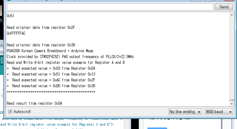 |
| Expected register values |
 |
| Returned values are correct |
Bravo!
TM's I2C Library Integration
Once I had confidence on my hardware, I compiled the software using TM's incredibly time saving and amazingly useful library. I ran it.
Nothing. no response. just plain nothing.
I checked to see whether the MCO1 (External Clock with an output of 22.5MHz) was properly set. It was. It's basically the heartbeat of the camera. You HAVE to give clock on the XCLK (External clock input) of the camera otherwise it won't work. Can't stress this enough.
I run again. No I2C response.
I lost confidence on my hardware.
Hardware Check: Pulling up that I2C line
[Pull up resistors basically does what it says, pull's up the line to logic high. This way it's not floating and is easy for the hardware to pull it down when I2C initiates. No errors.]
Technically speaking, the internal pull ups for the processor should have been enough. I didn't use external pull ups for the I2C communication while using with arduino and I didn't see a reason why I had to use an external pull up while using STM32F4xx processor.
I couldn't have been more wrong.
I had, somehow, thought about adding a 1.5K resistor to the I2C line on my schematics. Good thing, all I had to do was solder the two 1.5K resistors on the breakout board and test....
It worked. It really did work.
 |
| Without the pull up resistors (R3, R4) |
 |
| With the pull up resistors, after soldering |
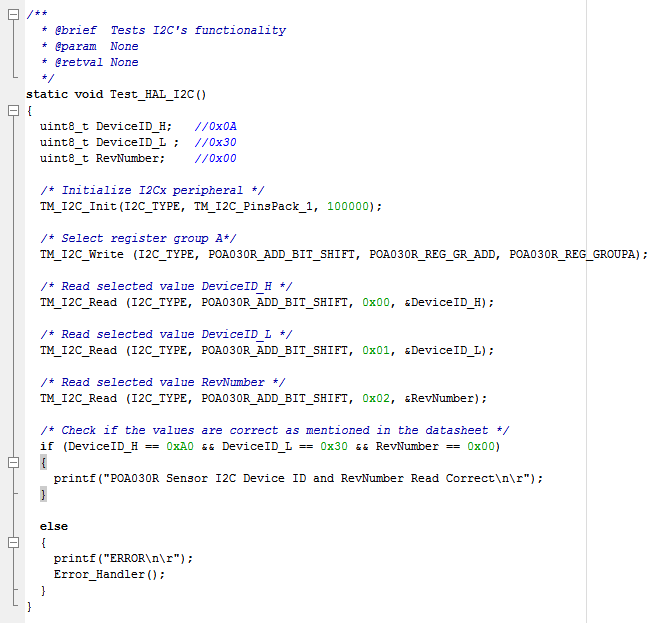 |
| Code for I2C check, you will notice that it should printf if all the values are correct will learn how to post code in blogger later |
 |
| And indeed it did! |
So the lesson here to take is that, it's a safe bet to place an external resistor even if the I2C line only has one slave. Usually the understanding is that an external pull up resistor is only required when there are more than one slave connected to the line as the total resistance drops as you add more slaves. Adding the external resistor would ensure it would remain logic level high, even if it's internally pulled. With STM32Fxx processors, its seen that you must place the external resistor for I2C to work.
Now to get that image data out and get the camera rolling..
one step at a time. every time.
one step at a time. every time.


Comments
Post a Comment